
|
Marine systems simulation
|
|
|
Marine systems simulation
|
 Collaboration diagram for Rudder:
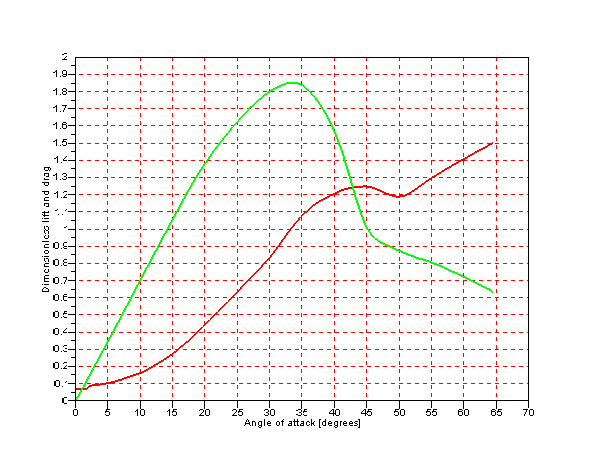
The simplified rudder model is based on lift and drag curves as a function of rudder angle. The orientation of the rudder is defined by vectors which define the stem axis around which the rudder rotate and the normal vector of the rudder surface. The rudder is a functional object and contain no internal state. The rudder is oriented and positioned form input ports.
The rudder area is partitioned in order to calculate the lift since the lift force is for the most part generated by the propeller by the incoming propeller jet stream. The incoming velocity is queries from the environment object at 21 evenly spaced points along the rudder stem in order to capture any variations in jet stream are by contraction of the propeller slipstream. The lift and drag force is calculated for slices of the rudder corresponding to the 21 incoming velocities and summarized to yield the final lift and drag force on the rudder.
| Name | Width | Description |
|---|---|---|
| RudderAngleBODY | 1 |
The rudder angle |
| VelocityNED | 3 |
The linear velocity of the rudder |
| PositionNED | 3 |
The position of the rudder |
| QuaternionNED | 4 |
The rotation quaternion of the body which the rudder is attached to |
| Name | Width | Description |
|---|---|---|
| ForceNED | 3 |
The force produced by the rudder in north-east-down coordinates |
| Name | Width | Description |
|---|---|---|
| Height | 1 |
The height of the rudder (foil breadth) |
| Chord | 1 |
The length of the rudder (foil chord) |
| Area | 1 |
The area of the rudder - if no Height and chord of the rudder is provided |
| Material | 1 | The material used to draw the propeller in the visualization |
| RudderType | 1 |
The rudder type, "2D" or "Curve", which controls the type of lift and drag input required |
| Alfa | 1 | The angle of attack of the \(C_l\) and \(C_t\) data, list of length \(N\). (Only appliccable for RudderType="Curve") |
| Cl | 1 | The lift coefficient of the rudder. Single value for 2D rudder or list of length \(N\) curve rudder |
| Cd | 1 | The drag coefficient of the rudder. Single value for 2D rudder or list of length \(N\) curve rudder |